NỘI DUNG CHÍNH
- 1 Kết nối Modbus RS 485
- 2 Bài viết liên quan
- 3 CÀI ĐẶT BIẾN TẦN Mitsubishi FR-D700 dùng modbus RS485
- 4 Setting parameter ( Cài đặt thông số )
- 4.1 Er4 Mode designation error ( Lỗi cài đặt )
- 4.2 (Pr. 77) Parameter write disable selection
- 4.3 Parameter clear/ All parameter clear ( Xoá tất cả thông số )
- 4.4 Pr.160 Extended parameter display (Pr. 160). Hiển thị thông số mở rộng
- 4.5 Pr.79 Operation mode selection Pr.79( chế độ)
- 4.6 Communication startup Pr.340 ( Khời động liên lạc )
- 4.7 P117 PU communication station number ( địa chỉ )
- 4.8 P118 PU communication speed ( tốc độ)
- 4.9 P119 PU communication stop bit length
- 4.10 P120 PU communication parity check ( kiểm tra chẵn lẻ và bit dừng)
- 4.11 P121 Number of PU communication retries
- 4.12 P122 PU communication check time interval
- 4.13 P549 Protocol selection ( Lựa chọn giao thức: RTU hay biến tần )
- 4.14 P340 Communication startupmode selection
- 5 Bài viết liên quan: video cài đặt Modbus RTU biến tần FR-D700
- 6 Modbus-RTU communication ( thiết lập truyền thông )
- 7 Modbus registers ( vùng địa chỉ chức năng modbus )
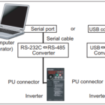
Kết nối Modbus RS 485
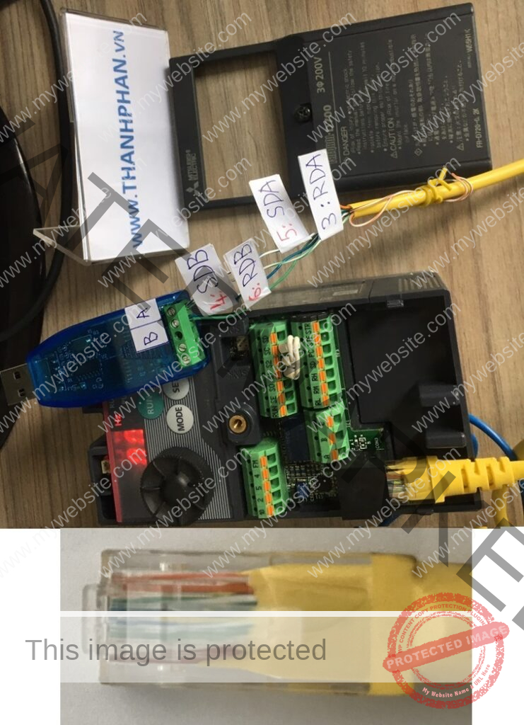
Jack kết nối Rj45 liên lạc RS485
Chú ý:
1. Không kết nối cổng PU này với cổng LAN của máy tính, điện thoại: có thể làm hư biến tần
2. Khi dùng truyền thông RS-485: không dùng chân 2 và chân 8
Cách làm cáp liên lạc cho biến tần :
Cách làm cáp liên lạc cho biến tần :
1. Mua dây cáp mạng bấm sẵn 2 đầu RJ45
2. Cắt dây ra: sử dụng 1 đầu RJ45
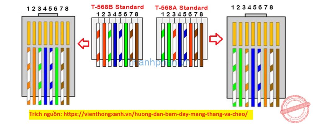
3. Xem màu dây trên đầu RJ45 theo tiêu chuẩn nào:
có 2 chuẩn: chuẩn T-568B và chuẩn T-568A
4. Xác định màu dây cho chân số 3, 4, 5 và 6.
Xem thêm: Dây Cáp 2 Lõi -22AWG-2C 2×0.35mm2 + shield + lá nhôm Vỏ PVC
Bài viết liên quan
Màn hình HMI YKHMI điều khiển biến tần Mitsubishi FR-D700 dùng modbus RS485. Chi tiết
Dùng phần mềm cài đặt biến tần Mitsubishi FR-D700
Làm Jack RS485 Modbus biến tần FR-D700
Cài đặt Modbus RTU biến tần FR-D700
Connection with RS-485 computer

Kết nối 2 dây RS485 và máy tính

Chân SDA <–> chân RDA <—> chân A
Chân SDB <–> chân RDB <—> chân B
Chân SDA, RDA và chân A kết nối chung với nhau
Chân SDB, RDB và chân B kết nối chung với nhau
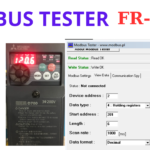
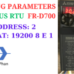
CÀI ĐẶT BIẾN TẦN Mitsubishi FR-D700 dùng modbus RS485
Cài đặt:
– Địa chỉ trạm: 2
– Giao thức: 19200, 8, E, 1
CHI TIẾT
Setting parameter ( Cài đặt thông số )
Er4 Mode designation error ( Lỗi cài đặt )
| Description Mô tả | Appears if a parameter setting is attempted in the External or NET operation mode with Pr. 77 ≠ “2”. Lỗi xuất hiện nếu cài đặt thông số khi đang ở chế độ External hoặc NET với Pr.77 ≠ “2” Appears if a parameter setting is attempted when the command source is not at the operation panel. Lỗi xuất hiện nếu cài đặt thông số khi không ở chế độ panel |
| Check point Kiểm tra | Check that operation mode is PU operation mode. Kiểm tra rằng chế độ hoạt động là PU Check the Pr. 77 setting. (Refer to page 162). Kiểm tra thông số Pr.77 bên dưới Check if a parameter unit (FR-PU04/FR-PU07) is connected when Pr. 551 = “9999 (initial setting).” Check the Pr. 551 setting. Kiểm tra nếu (FR-PU04/FR-PU07) được kết nối khi Pr.551 = “9999” |
| Corrective action Khắc phục | After setting the operation mode to the “PU operation mode”, make parameter setting. (Refer to page 166) Sau khi thiết lập chế độ hoạt động PU, thực hiện cài đặt thông số After setting Pr. 77 = “2”, make parameter setting. Sau khi cài đặt Pr. 77 = “2”, thực hiện cài đặt thông số Disconnect the parameter unit (FR-PU04/FR-PU07), and make parameter setting. Ngắt kết nối FR-PU04/FR-PU07, thực hiện cài đặt thông số” After setting Pr. 551 = “4”, make parameter setting. (Refer to page 175) Sau khi thiết lập Pr. 551 = “4”, thực hiện cài đặt thông số |
(Pr. 77) Parameter write disable selection
| 0 | Write is enabled only during stop. Cho phép cài đặt trong lúc biến tần dừng |
| 1 | Parameter can not be written. Không cho cài đặt thông số |
| 2 | Parameter write is enabled in any operation mode regardless of operation status Cho phép cài đặt trong bất kỳ chế độ nào trừ khi trạng thái hoạt động |
Parameter clear/ All parameter clear ( Xoá tất cả thông số )

Chân Pr.CL: parameter clear ( xoá thông số )
Chân ALLC: ALL parameter clear ( xoá TẤT CẢ thông số )
Chọn 1 để xoá thông số
Pr.160 Extended parameter display (Pr. 160). Hiển thị thông số mở rộng
Pr. 160 = 9999 ( mặc định )
9999: Displays only the simple mode parameters ( hiển thị chỉ thông số chế độ cơ bản )
0: Displays simple mode + extended parameters ( hiển thị: thông số chế độ cơ bản và thông số mở rộng )
–> Chọn 0
Pr.79 Operation mode selection Pr.79( chế độ)
| 0 ( Mặc định Default ) | Use External/PU switchover mode (PU/EXT ) to switch between the PU and External operation mode. Dùng nút PU/EXT để chuyển qua lại giữa chế độ PU và EXT At power ON, the inverter is in the External operation mode. Mở nguồn lên, biến tần vào chế độ EXT |
| 1 | Fixed to PU operation mode Chế độ PU cố định |
| 2 | Fixed to External operation mode Operation can be performed by switching between the external and NET operation mode. Chế độ EXT cố định |
| 3 | Frequency command Operation panel and PU (FRPU04/FR-PU07) setting or external signal input (multi-speed setting, across terminals 4-5 (valid when AU signal turns ON)). Start command External signal input (terminal STF, STR) |
| 4 | Frequency command External signal input (terminal 2, 4, JOG, multi-speed selection, etc.) Start command Enter from RUN of the operation panel and FWD and REV of the PU (FR-PU04/FR-PU07) |
| 6 | Switchover mode Switchover among PU operation, External operation, and NET operation is available while keeping the same operation status. |
| 7 | External operation mode (PU operation interlock) X12 signal ON Operation mode can be switched to the PU operation mode. (output stop during External operation) X12 signal OFF Operation mode can not be switched to the PU operation mode. |
Communication startup Pr.340 ( Khời động liên lạc )
| 0 ( Mặc định Default ) | As set in Pr. 79. Theo cài đặt của Pr.79 |
| 1 | Network operation mode Chế độ NET mạng |
| 10 | Network operation modeOperation mode can be changed between the PU operation mode and Network operation mode from the operation panel |
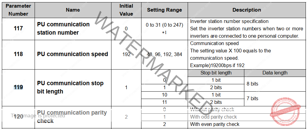
P117 PU communication station number ( địa chỉ )
P117 = 0 ( mặc định )
0: No reply to the master
1 to 247 Set the inverter station numbers ( số trạm )
–> chọn số trong phạm vi 1-247
P118 PU communication speed ( tốc độ)
P118 = 192 ( mặc định )
Range: 48, 96 , 192 , 384 . Communication speed
The setting value × 100 equals the communication speed. Example: 9600bps if 96
( 192: 192 x 100 = 19200 bps )
P119 PU communication stop bit length
| Stop bit length | Data length | |
| 0 | 1 bit | 8 bits |
| 1 mặc định Default | 2 bits | 8 bits |
| 10 | 1 bit | 7 bits |
| 11 | 2 bits | 7 bits |
P120 PU communication parity check ( kiểm tra chẵn lẻ và bit dừng)
P120 = 2 ( mặc định)
Range: 0, 1, 2
0:Without parity check
Stop bit length 2 bits ( none, 2 bit )
1:With odd parity check
Stop bit length 1 bit ( odd, 1 bit )
2:With even parity check
Stop bit length 1 bit ( even, 1 bit )
P121 Number of PU communication retries
Default mặc định :1
0 to 10: Number of retries at data receive error occurrence. If the number of
consecutive errors exceeds the permissible value, the inverter will
come to trip (depends on Pr. 502). Valid only Mitsubishi inverter (computer link operation) protocol
9999: If a communication error occurs, the inverter will not come to trip. (NET
operation mode at initial value)
Có lỗi xảy ra , biến tần không TRIP
P122 PU communication check time interval
0: RS-485 communication can be made. Note that a communication fault
(E.PUE) occurs as soon as the inverter is switched to the operation
mode with command source. (NET operation mode at initial value)
0.1 to 999.8s: Communication check (signal loss detection) time interval
If a no-communication state persists for longer than the permissible
time, the inverter will come to trip (depends on Pr. 502).
9999 No communication check (signal loss detection)
Không kiểm tra mất tín hiệu
P549 Protocol selection ( Lựa chọn giao thức: RTU hay biến tần )
P549 = 0 ( mặc định )
0 Mitsubishi inverter (computer link operation) protocol
1 Modbus-RTU protocol
P340 Communication startupmode selection
| 0 | As set in Pr. 79. Theo cài đặt Pr. 79 |
| 1 | Network operation mode Chế độ mạng |
| 10 | Network operation mode Operation mode can be changed between the PU operation mode and Network operation mode from the operation panel. Chế độ mạng NET, chế độ PU có thể thay đổi từ bảng điều khiển: nút PU/EXT |
Bài viết liên quan: video cài đặt Modbus RTU biến tần FR-D700
Modbus-RTU communication ( thiết lập truyền thông )
Xác định liên lạc

Danh sách các thông số:
- Pr.549: Giao thức Modbus
- Pr.117: Địa chỉ thiết bị
- Pr.118: tốc độ liên lạc
- Pr.120: chiều dài bit, kiểm tra chẳn lẽ
Đặc điểm Modbus biến tần
Biến tần Mitsubishi FR-D700:
– Chỉ hỗ trợ Modbus RTU mà 1 byte ( 8-bit) dữ liệu được truyền
– Cho phép đọc và ghi giá trị thông số của biến tần, ghi lệnh điều khiển biến tần và kiểm tra trạng thái hoạt động.
– Dữ liệu biến tần được chứa trong thanh ghi Holding resgister có địa chỉ: 40001 đến 49999
Khung message có 4 trường:
- Địa chỉ thiết bị . Device Address
- Hàm chức năng. Function code.
- Byte dữ liệu. Data bytes.
- Kiểm tra lỗi. Error check.

Address ( địa chỉ )
Là byte dài 8 bits và có thể cài đặt địa chỉ 0 đến 247.
The address code is 1 byte long ( 8 bits ) and any of 0 to 247 can be set.
Function code ( Hàm chức năng )
| code | Function name | Outline |
| H03 | Read Holding Register | Reads the holding register data. Đọc thanh ghi dữ liệu |
| H06 | Preset Single Register | Writes data to the holding register. Ghi dữ liệu đến 1 thanh ghi |
| H08 | Diagnostics | Function diagnosis (communication check only) |
| H10 | Preset Multiple Registers | Writes data to multiple consecutive holding registers Ghi dữ liệu đến nhiều thanh ghi |
| H46 | Read Holding Register Access Log | Reads the number of registers that succeeded in communication last time |
- 03H: multi read, read data from registers.
- 06H: single write, write single data to register.
- 08H: loop detection, this command is used to test if the communication between
master equipment (PC or PLC) and AC drive is normal or not. AC drive will
send the data received from master equipment back to master equipment. - 10H: multi write, write multi data to registers.
DATA field
Định dạng phụ thuộc vào hàm chức năng ( function code ). Dữ liệu gồm điếm byte, số byte, mô tả theo thanh ghi ( holding register )
CRC CHECK filed
Khung thông điệp ( message ) nhận được thì được kiểm tra lỗi. Kiểm tra CRC được thực hiện và dữ liệu dài 2 byte được thêm vào phần cuối của thông điệp. Khi CRC được thêm vào , byte thấp phía trước, byte cao phía sau.
Giá trị CRC được tính toán bởi bên gửi và thêm giá trị CRC này vào thông điệp. Bên nhân tính toán lại giá trị CRC trong lúc nhận được thông điệp và so sánh giá trị tính toán đó với giá trị CRC trong trường CRC CHECK. Nếu hai giá trị này khác nhau, kết quả là lỗi.
(5) Message format types
Read holding register data (H03 or 03)
Can read the description of 1) system environment variables, 2) real-time monitor, 3) faults history, and 4) inverter parameters assigned to the holding register area (refer to the register list (page 208))
- Môi trường hệ thống
- Giám sát thời gian thực
- Lịch sử lỗi
- Thông số biến tần được gán theo thanh ghi
Query message setting
| Message | Setting description |
| 1. Slave address |
Address to which the message will be sent |
| 2. Function |
Set H03 |
| 3. Starting address |
Set the address at which holding register data read will be started. |
| 4. No. of Points | Number of holding registers from which data will be read The number of registers from which data can be read is a maximum of 125. Số thanh ghi holding register mà dữ liệu sẽ được đọc. số tối đa là 125 |
Description of normal response
| 5. Byte Count |
The setting range is H02 to HFA (2 to 250). |
| 6. Data: Read data |
The number of data specified at 4) is set. Data are read in order of Hi byte and Lo byte, and set in order of starting address data, starting address + 1 data, starting address + 2 data |
Example: To read the register values of 41004 (Pr. 4) to 41006 (Pr. 6) from the slave address 17 (H11)
Đọc giá trị thanh ghi 41004 (Pr. 4) to 41006 (Pr. 6) từ thiết bị slave có địa chỉ 17 (H11)
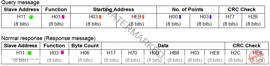
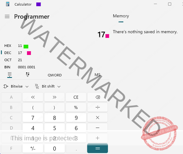
The slave address, địa chỉ slave 17 (số thập phân) => số Hex: H11
Starting address ( địa chỉ bắt đầu )= 41004 – 40001 = 1003 (số thập phân)
=>số thập phân: 1003 => số Hex: H3EB –> H03 HEB
No. of Points ( Number of holding registers, Số thanh ghi holding register ) :
41004, 41005, và 41006 : 3 (số thập phân)–> số Hex: H3 => H00 H03
Read value
Register 41004(Pr. 4): H1770 (60.00Hz)
Register 41005(Pr. 5): H0BB8 (30.00Hz)
Register 41006(Pr. 6): H03E8 (10.00Hz)
Đọc giá trị:
1. Thanh ghi 41004(Pr. 4) có địa chỉ số thập phân 1003: giá trị thập phân 60.00 Hz
=> số Hex: H1770. Tương ứng: 6000 vì modbus hiển thị số nguyên.
2. Thanh ghi 41005(Pr. 5) có địa chỉ số thập phân 1004: giá trị thập phân 30.00 Hz
=> số Hex: H0BB8. Tương ứng: 3000 vì modbus hiển thị số nguyên.
2. Thanh ghi 41006(Pr. 6) có địa chỉ số thập phân 1005: giá trị thập phân 10.00 Hz
=> số Hex: H03E8. Tương ứng: 1000 vì modbus hiển thị số nguyên.
Write holding register data (H06 or 06)
Can write the description of 1) system environment variables and 4) inverter parameters assigned to the holding
register area (refer to the register list ( page 208)).Môi trường hệ thống
1. Môi trường hệ thống
4.Thông số biến tần được gán theo thanh ghi
| Message | Setting description |
| 1. Slave address |
Address to which the message will be sent |
| 2. Function |
Set H06 |
| 3. Register address |
Address of the holding register to which data will be written. |
| 4. Preset Data |
Data that will be written to the holding register |
Example: To write 60Hz (H1770) to 40014 (running frequency RAM) at slave address 5 (H05).
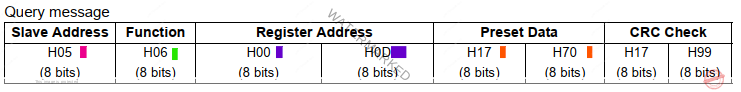
The slave address, địa chỉ slave 5 (số thập phân) => số Hex: H05
Register address ( địa chỉ thanh ghi )= 40014 – 40001 = 0013 (số thập phân)
=>số thập phân: 0013 => số Hex: H000D –> H00 H0D
Preset data
60 Hz (số thập phân) = 60.00 Hz. Hiển thị modbus: 6000–> số Hex: H1770 => H17 H70
Write multiple holding register data (H10 or 16)
You can write data to multiple holding registers.
Bạn có thể ghi dữ liệu đến nhiều thanh ghi.
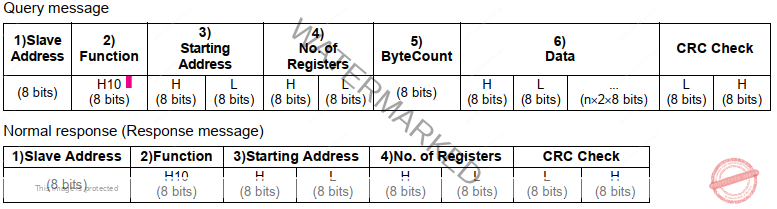
Query message setting
| Message | Setting description |
| 1. Slave address |
Address to which the message will be sent |
| 2. Function |
Set H10 |
| 3. Starting address |
Address where holding register data write will be started. |
| 4. No. of Points | Number of holding registers where data will be write The number of registers where data can be written is a maximum of 125. |
| 5. Byte Count |
The setting range is H02 to HFA (2 to 250). |
| 6. Data | Set the data specified by the number specified at 4). The written data are set in order of Hi byte and Lo byte, and arranged in order of the starting address data, starting address + 1 data, starting address + 2 data |
Example: To write 0.5s (H05) to 41007 (Pr. 7) at the slave address 25 (H19) and 1s (H0A) to 41008 (Pr.8)
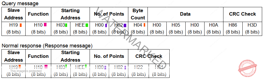
The slave address, địa chỉ slave 25 (số thập phân) => số Hex: H19
Register address ( địa chỉ thanh ghi )= 41007 – 40001 = 1006 (số thập phân)
=>số thập phân: 1006 => số Hex: H03FE –> H03 HFE
Data
0.5 S (số thập phân) = 000.5 S . Hiển thị modbus: 0005–> số Hex: H05 => H00 H05
1.0 S (số thập phân) = 001.0 S . Hiển thị modbus: 0010–> số Hex: H0A => H00 H0A
Modbus registers ( vùng địa chỉ chức năng modbus )
System environment variable ( Điều khiển)
| Register | Definition | Read/Write | Remark |
| 40002 | inverter reset reset biến tần | Write ghi | Any value can be written |
| 40003 | Parameter clear | Write | Set H965A as a written value. |
| 40004 | All parameter clear Xoá thông số | Write | Set H99AA as a written value |
| 40006 | Parameter clear ∗1 | Write | Set H5A96 as a written value |
| 40007 | All parameter clear ∗1 | Write | Set HAA99 as a written value |
| 40009 | Inverter status/control input instruction∗2 Trạng thái biến tần Lệnh điều khiển | Read/write Đọc/Ghi | See below. Xem bảng 1 bên dưới |
| 40010 | Operation mode/inverter setting ∗3 Chế độ hoạt động | Read/write Đọc/Ghi | See below. Xem bảng 2 bên dưới |
| 40014 | Running frequency (RAM value) Tần số chạy ( RAM) Tần số cài đặt setting frequency | Read/write Đọc/Ghi | According to the Pr. 37 settings, the frequency and selectable speed are in 1r/min increments |
| 40015 | Running frequency (EEPROM value) Tần số chạy ( EEPROM) | Write Ghi |
Trạng thái biến tần/Lệnh điều khiển Thanh ghi 40009
| Bit | Control input instruction Lệnh điều khiển | Inverter status Trạng thái biến tần |
| 0 | Stop command Lênh dừng | RUN (inverter running) ∗2 Đang chạy |
| 1 | Forward rotation command Lệnh chạy thuận | During forward rotation Đang chạy thuận |
| 2 | Reverse rotation command Lệnh chạy ngược | During reverse rotation Đang chạy nghịch |
| 3 | RH (high-speed operation command)∗1 | SU (up-to-frequency) |
| 4 | RM (middle-speed operation command)∗1 | OL (overload) |
| 5 | RL (low-speed operation command)∗1 | 0 |
| 6 | 0 | FU (frequency detection) |
| 7 | RT (second function selection) | ABC (fault) ∗2 |
| 8 | AU (terminal 4 input selection) | 0 |
| 9 | 0 | SO (safety monitor output) ∗2 |
| 10 | MRS (output stop) | 0 |
| 11 | 0 | 0 |
| 12 | 0 | 0 |
| 13 | 0 | 0 |
| 14 | 0 | 0 |
| 15 | 0 | Fault occurrence |
Bảng lệnh điều khiển Thanh ghi 40009
Chế độ hoạt động / Cài đặt biến tần Thanh ghi 40010
| Mode | Read Value Đọc | Written Value Ghi |
| EXT | H0000 | H0010 * |
| PU | H0001 | H0011 * |
| EXT JOG | H0002 | — |
| NET | H0004 | H0014 |
| PU+EXT | H0005 | — |
Chế độ hoạt động / Cài đặt biến tần
Real time monitor ( giám sát thời gian thực, chế độ: đọc)
| Register thanh ghi | Description mô tả | Unit Đơn vị | ||||||||
| 40201 | Output frequency/speed ∗4 0.01Hz/1 ∗1 tần số xuất ra / tốc độ | Output frequency/speed ∗4 0.01Hz/1 ∗1 | ||||||||
| 40202 | Output current ∗4 Dòng điện xuất ra | 0.01A | ||||||||
| 40203 | Output voltage ∗4 Điện áp xuất ra | 0.1V | ||||||||
| 40205 | Output frequency setting/speed setting Tần số cài đặt xuất ra | 0.01Hz/1 ∗1 | ||||||||
| 40208 | Converter output voltage Điện áp xuất ra biến đổi | 0.1V | ||||||||
| 40209 | Regenerative brake duty | 0.1% | ||||||||
| 40210 | Electronic thermal relay function load factor | 0.1% | ||||||||
| 40211 | Output current peak value | 0.01A | ||||||||
| 40212 | Converter output voltage peak value | 0.1V | ||||||||
| 40214 | Output power | 0.01kW | ||||||||
| 40215 | Input terminal status ∗2 | — | ||||||||
| 40216 | Output terminal status ∗3 | — | ||||||||
| 40220 | Cumulative energization time | 1h | ||||||||
| 40223 | Actual operation time | 1h | ||||||||
| 40224 | Motor load factor | 0.1% | ||||||||
| 40225 | Cumulative power | 1kWh | ||||||||
| 40252 | PID set point | 0.1% | ||||||||
| 40253 | PID measured value | 0.1% | ||||||||
| 40254 | PID deviation | 0.1% | ||||||||
| 40261 | Motor thermal load factor | 0.1% | ||||||||
| 40262 | Inverter thermal load factor | 0.1% | ||||||||
| 40263 | Cumulative power 2 | 0.01kWh | ||||||||
40264 | PTC thermistor resistance | 0.01kΩ |
Xem thêm tài liệu Modbus Biến tần Mitsubishi FR-D700. Chi tiết
Thông số cài đặt biến tần P1 / setting parameter P7
Parameter: 0 – 999: the parameter number + 41000 is the register number
Thanh ghi = thông số cài đặt + 41000
Tham khảo trang 58 cài đặt thông số. Refer page 58 for setting parameters
Ví dụ:
| Register thanh ghi | Description mô tả | Unit Đơn vị | ||||||||
| 41000 | P0: Torque boost | 0.1% | ||||||||
| 41001 | P1: Maximum frequency Tần số tối đa | 0.01Hz | ||||||||
| 41002 | P2: Minimum frequency Tần số nhỏ nhất | 0.01Hz | ||||||||
| …. | ||||||||||
| 41007 | P7: Acceleration time Thời gian tăng tốc | 0.1s | ||||||||
| 41008 | P8: Acceleration time Thời gian giảm tốc | 0.1S | ||||||||
Đang cập nhật
Các bạn có thắc mắc: vui lòng để lại bình luận bên dưới. Chúng tôi sẽ phản hồi trong thời gian sớm nhất